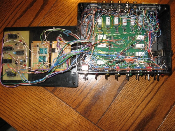
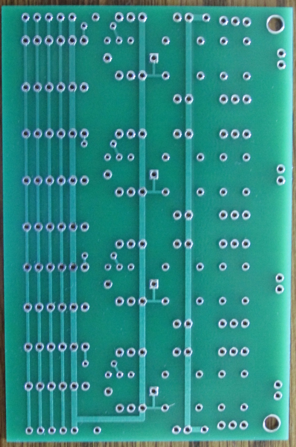
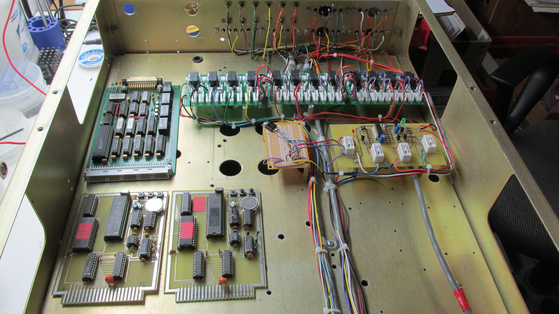
 I have designed a custom relay boards using higher rated relays and incorporating a lot of interconnections
onto the board which should lead to simplified interconnecting wires. A new DEMI sequencer was built
to increase reliability and retire the old sequencer that had several burned components replaced.
I have designed a custom relay boards using higher rated relays and incorporating a lot of interconnections
onto the board which should lead to simplified interconnecting wires. A new DEMI sequencer was built
to increase reliability and retire the old sequencer that had several burned components replaced.
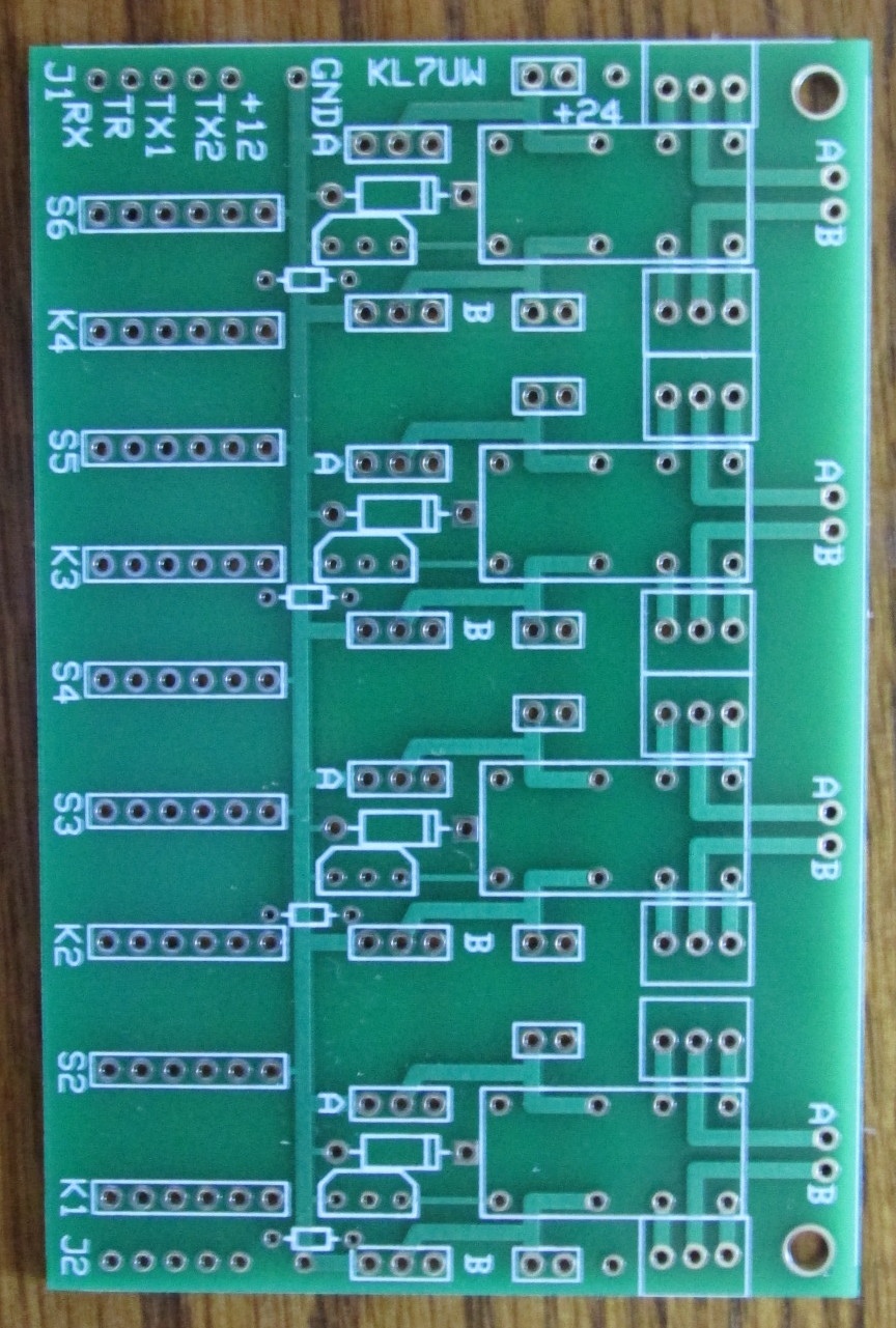

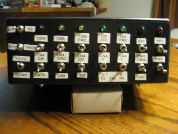
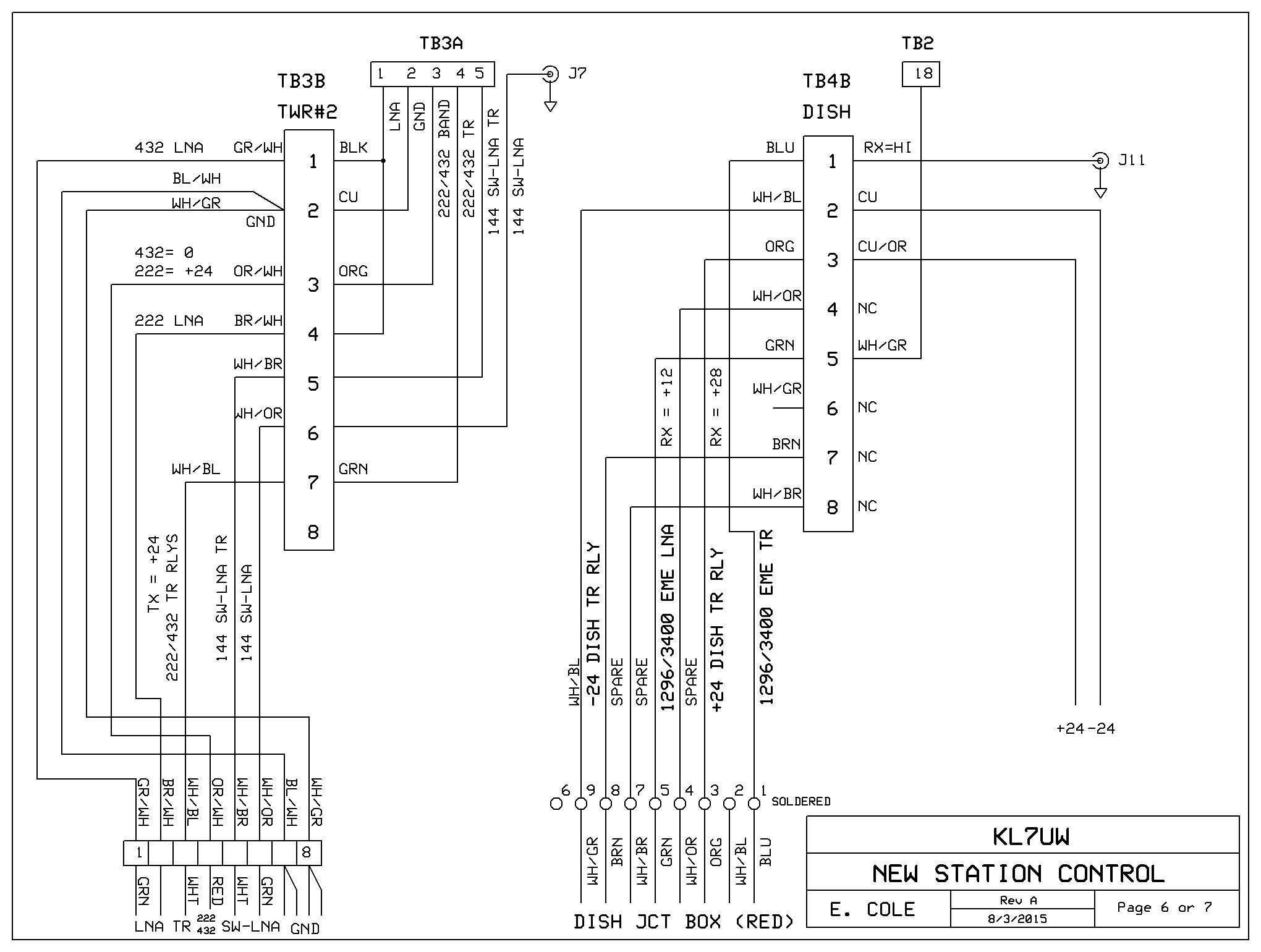
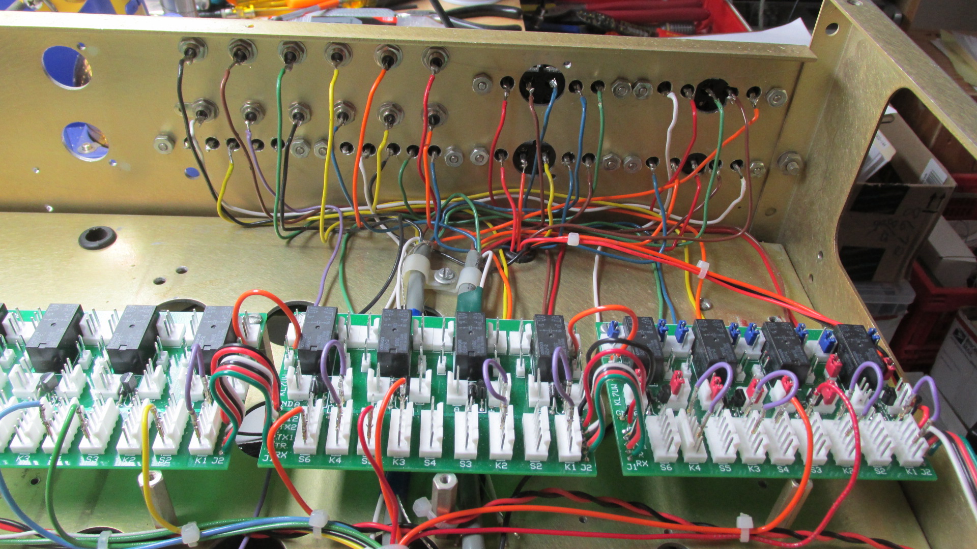
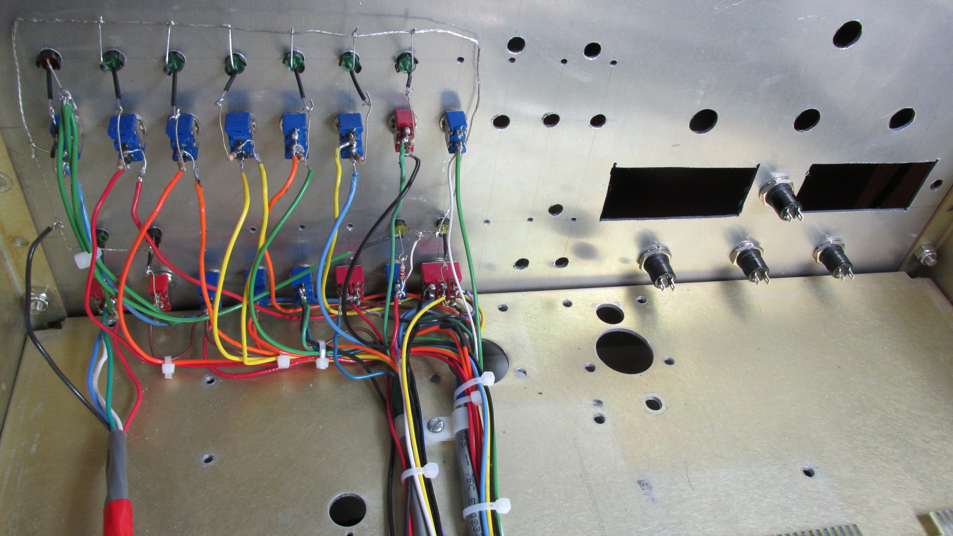
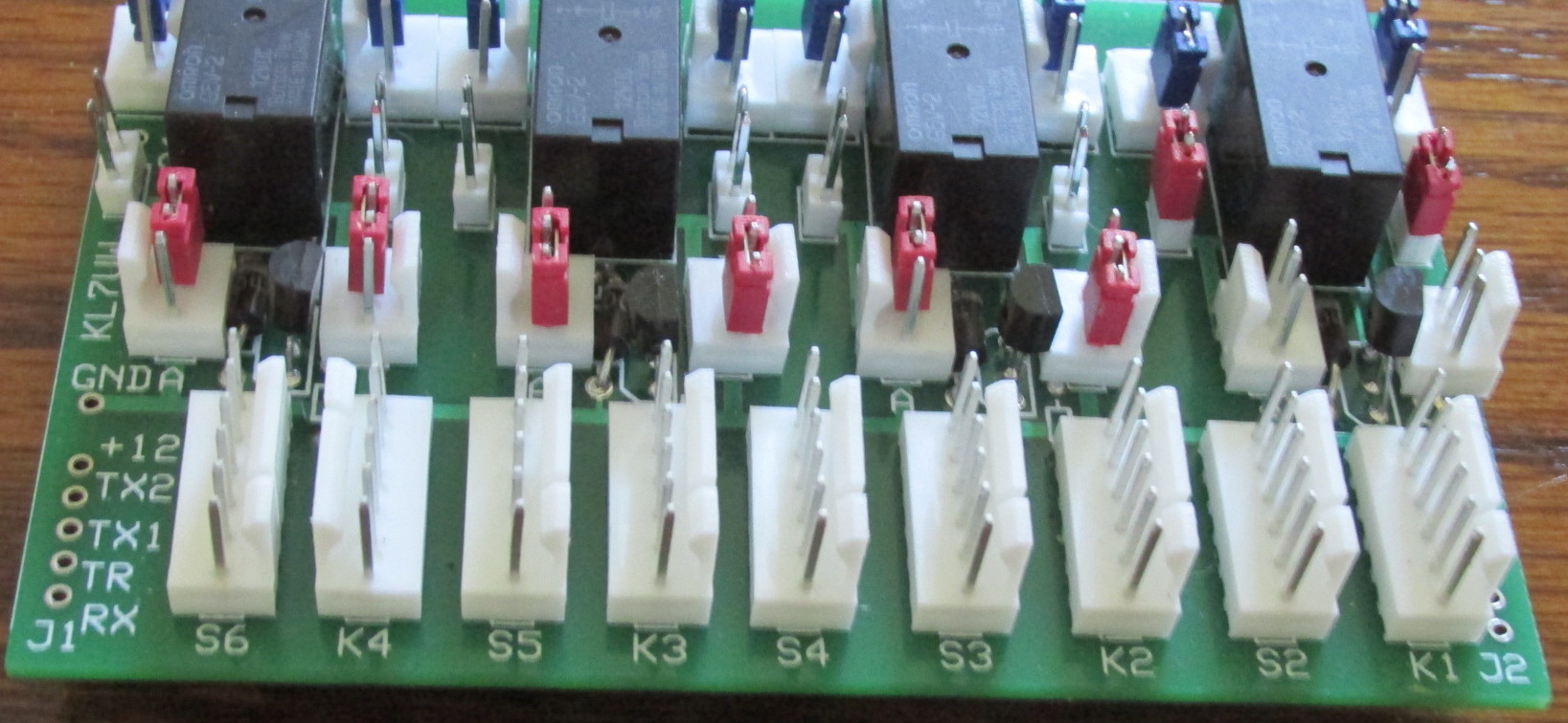 The conrol panel will have three relay boards (twelve DPDT relays). The boards are provided with risers
for configuring the relay drive source, common and NO and NC terminals. Small shorting jumpers and
short jumper wires will be used on the risers. Seven line buss provides +12, +24, ground, Rx,TR, Tx1, and Tx2
connections. The buss continues across all three relay boards via ribbon wire jumpers. 8-conductor No. 20 wire
cable is used for the interconnections between the 16 switches, three terminal boards, and 12 RCA connectors.
A new inhibit board will be designed to replace the Radio Shack project boards currently in use.
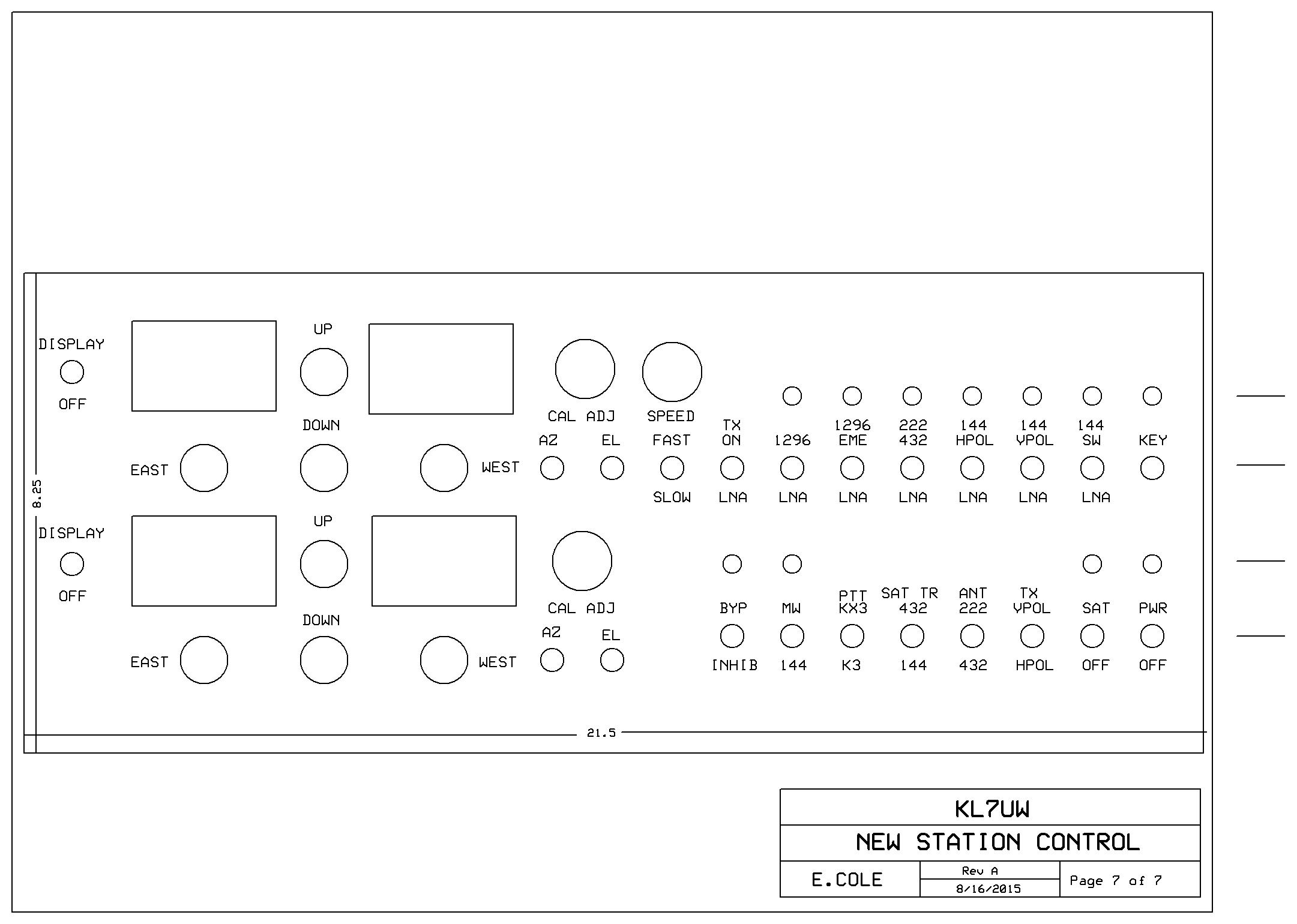
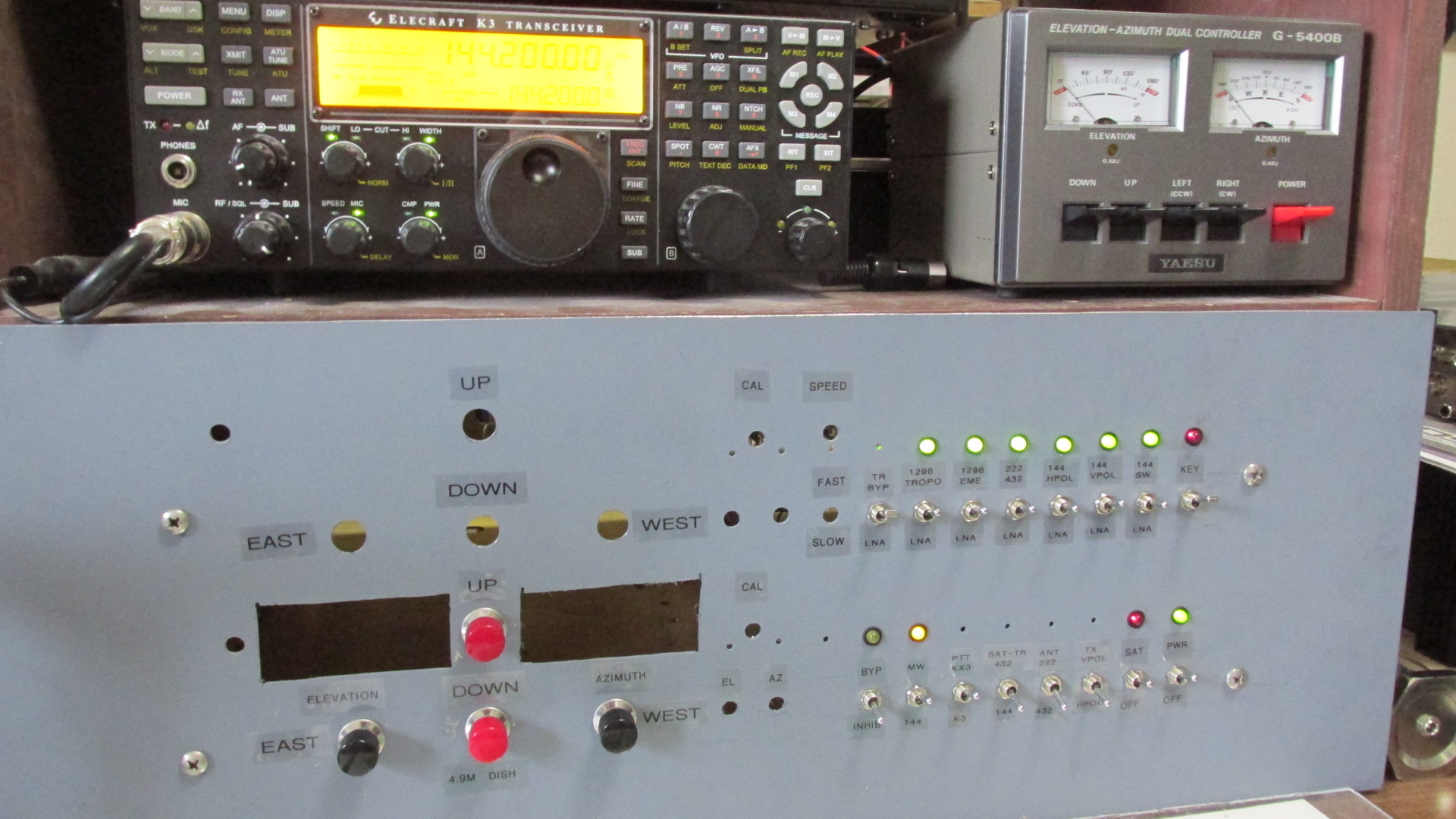
The contoller enclosure is much larger and will also include the digital angle encoder boards and autotrack
interface board, with LED angle displays and controls for setting the encoders, plus push buttons for manual
control of the dish and 2m-eme antennas.
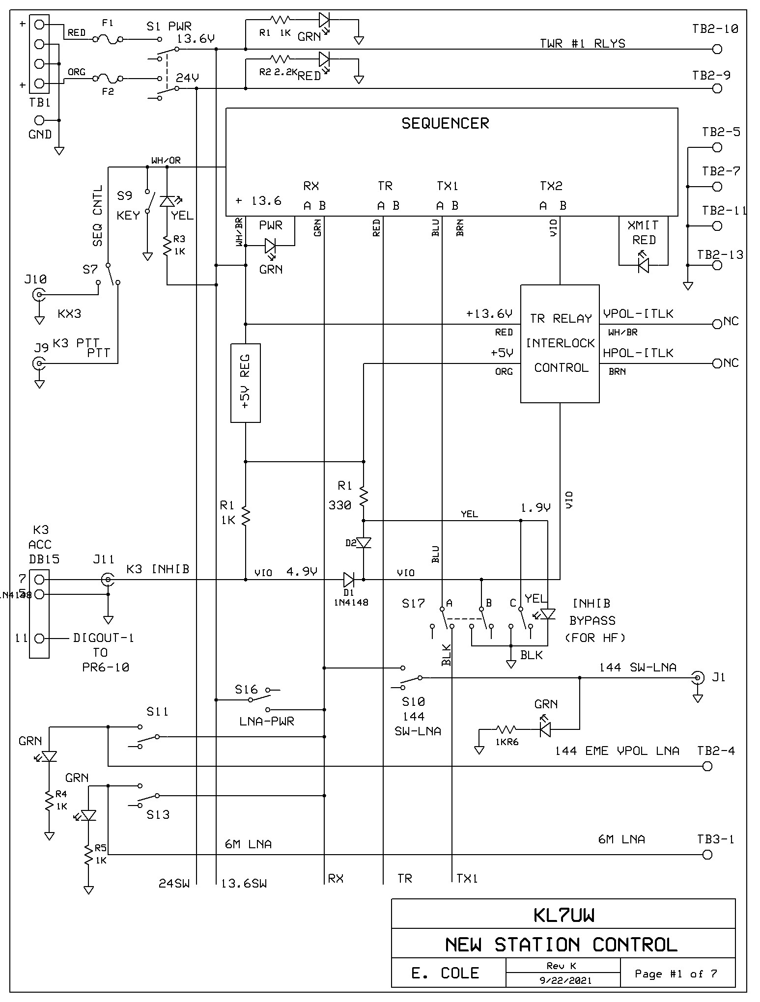
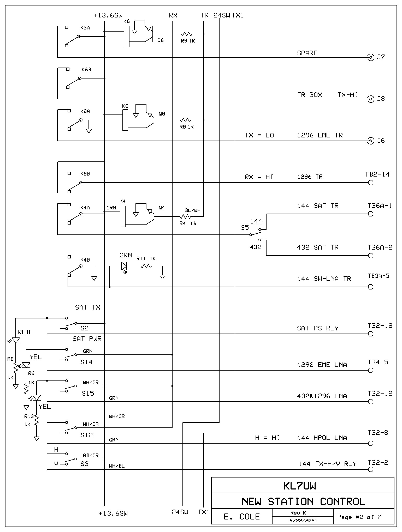
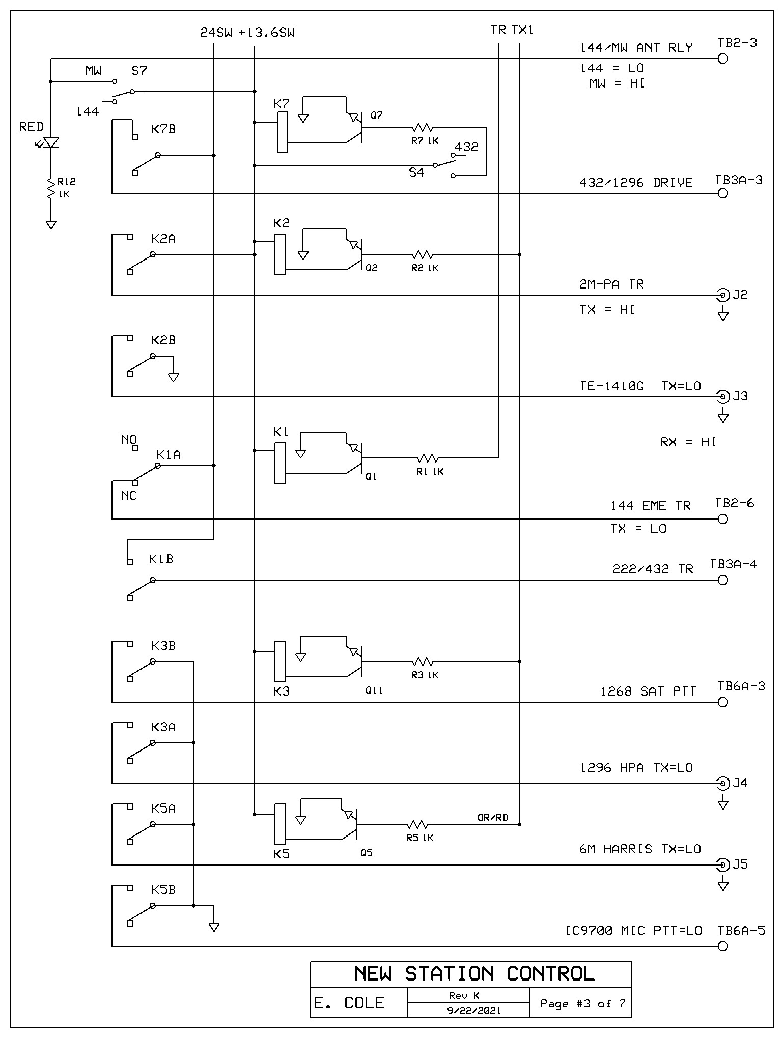
Diagrams and Drawings:
The conrol panel will have three relay boards (twelve DPDT relays). The boards are provided with risers
for configuring the relay drive source, common and NO and NC terminals. Small shorting jumpers and
short jumper wires will be used on the risers. Seven line buss provides +12, +24, ground, Rx,TR, Tx1, and Tx2
connections. The buss continues across all three relay boards via ribbon wire jumpers. 8-conductor No. 20 wire
cable is used for the interconnections between the 16 switches, three terminal boards, and 12 RCA connectors.
A new inhibit board will be designed to replace the Radio Shack project boards currently in use.
The contoller enclosure is much larger and will also include the digital angle encoder boards and autotrack
interface board, with LED angle displays and controls for setting the encoders, plus push buttons for manual
control of the dish and 2m-eme antennas.
Diagrams and Drawings:


 New Photos:
Return to Home Page