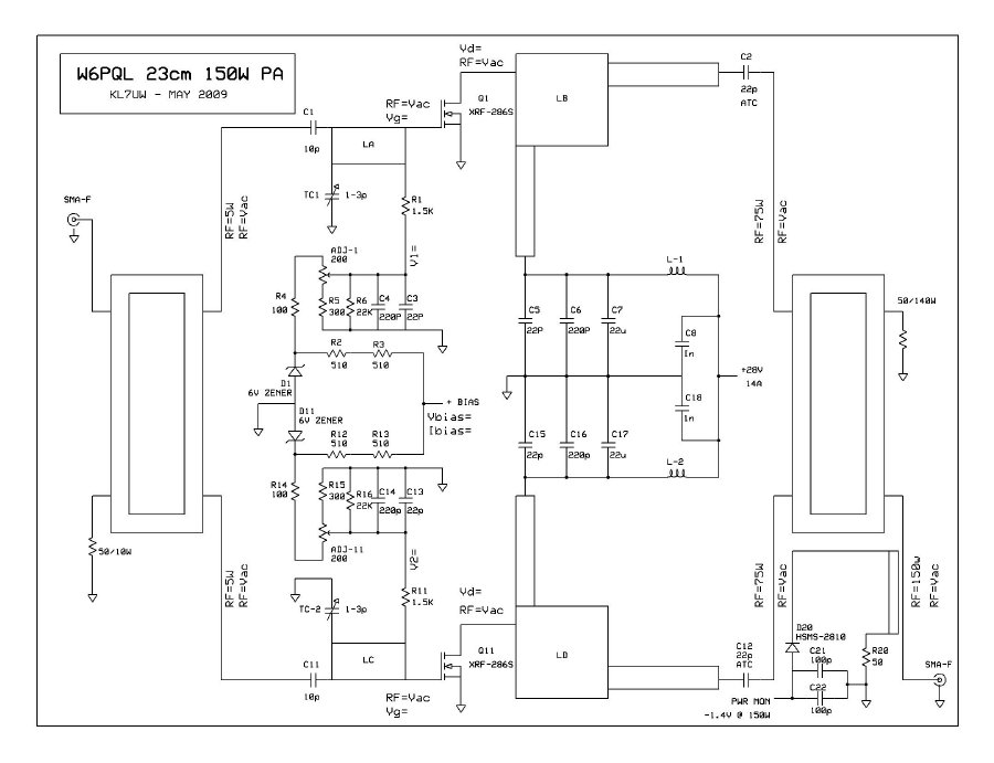
Schematic Diagram of 150w board:
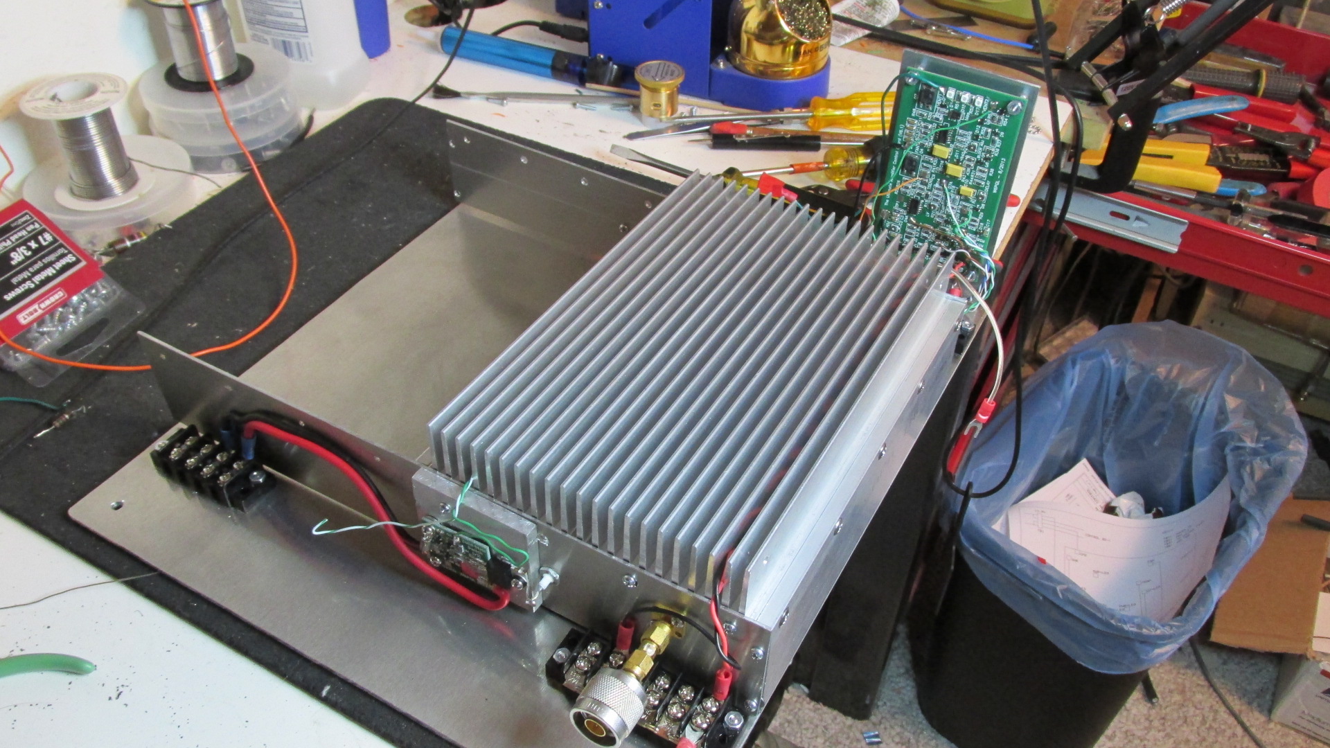
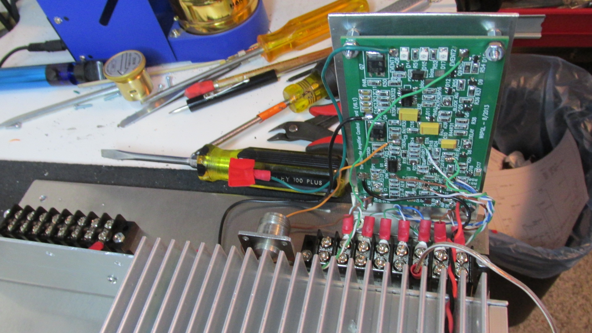
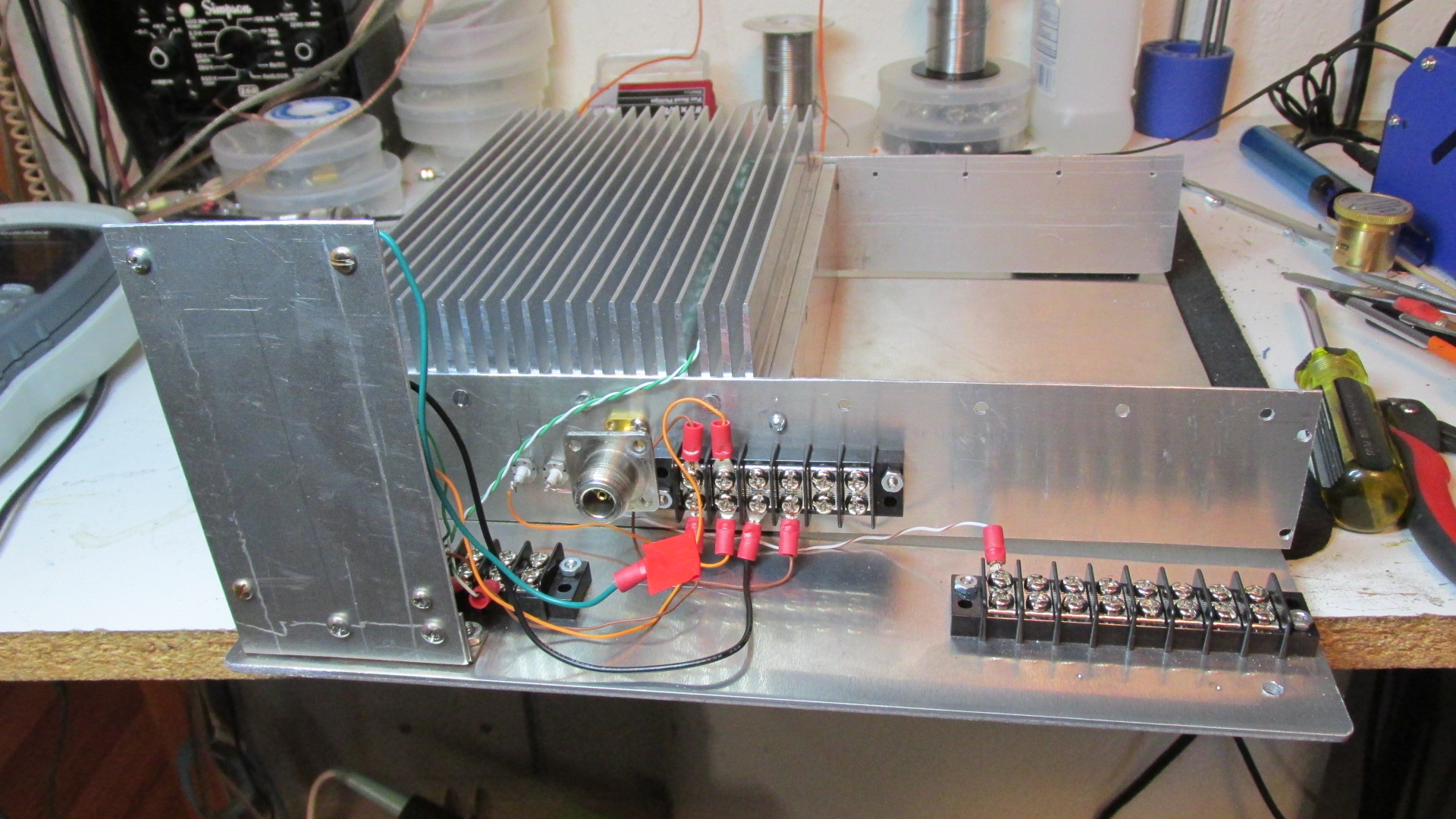
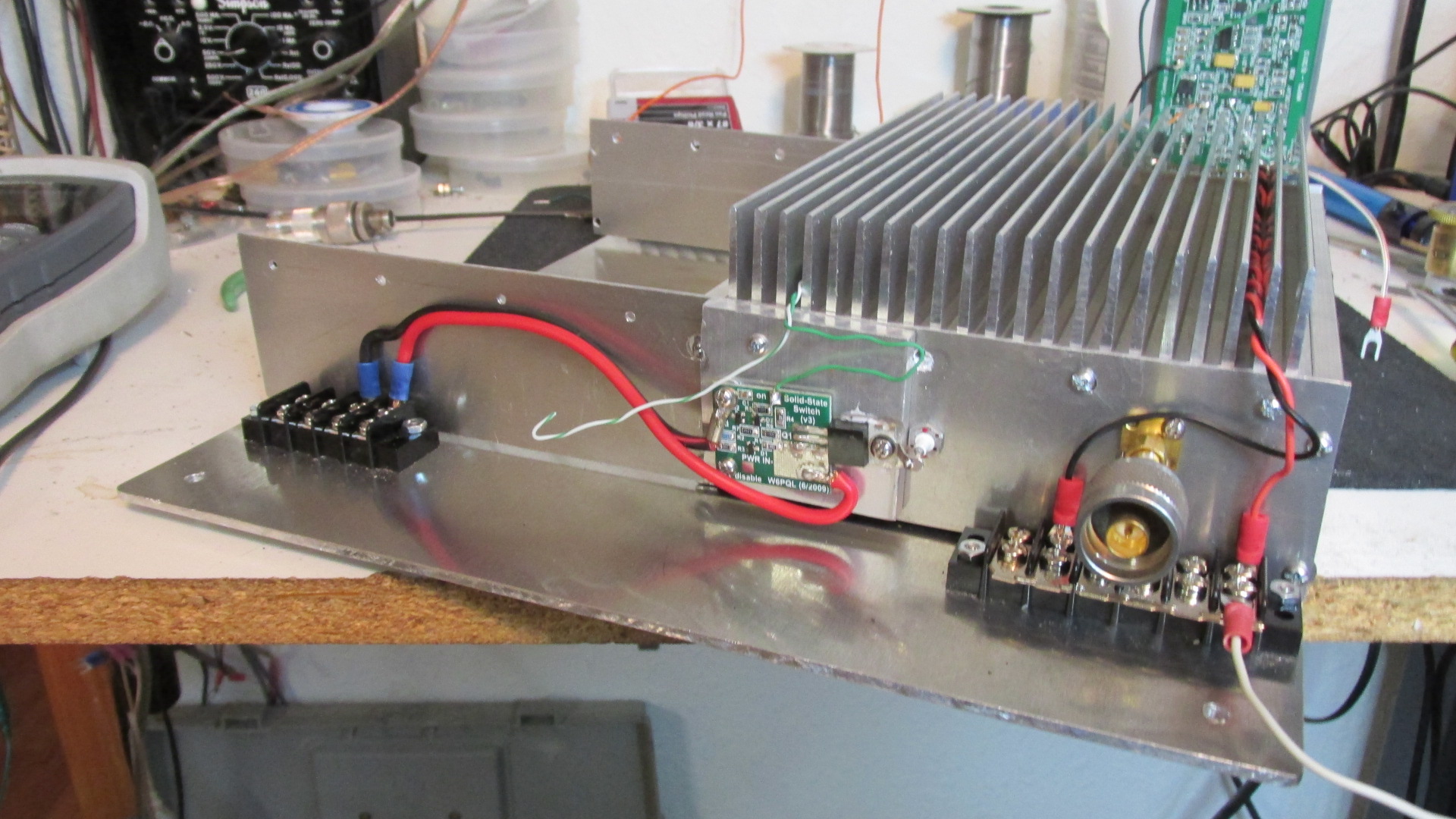
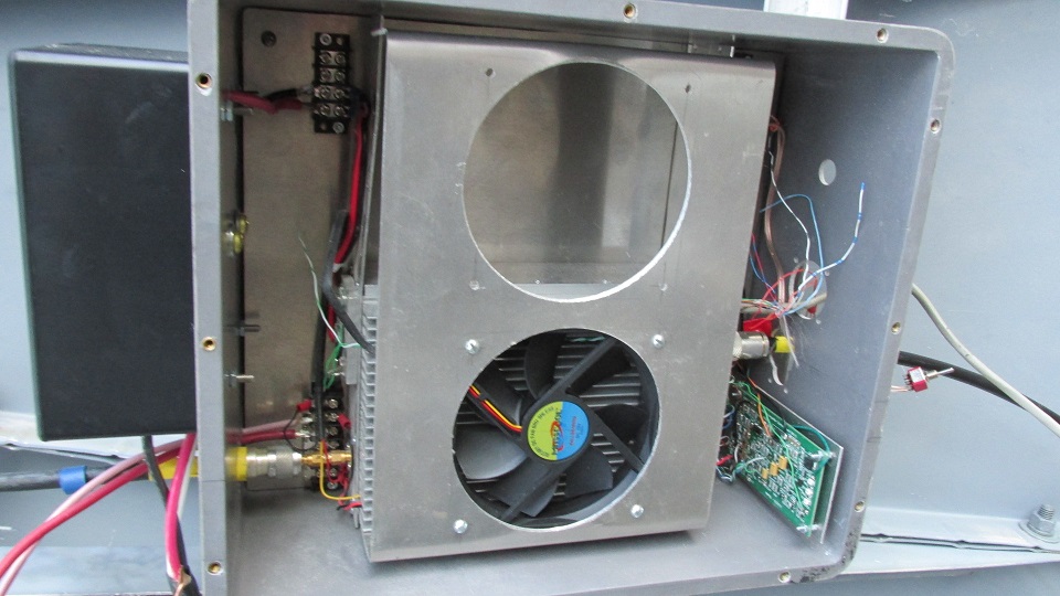
Photos:
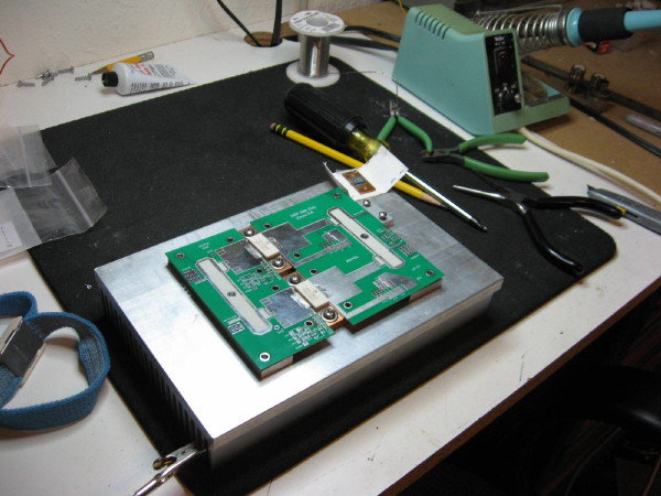
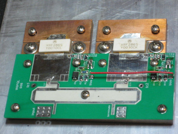
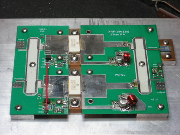
 "
"

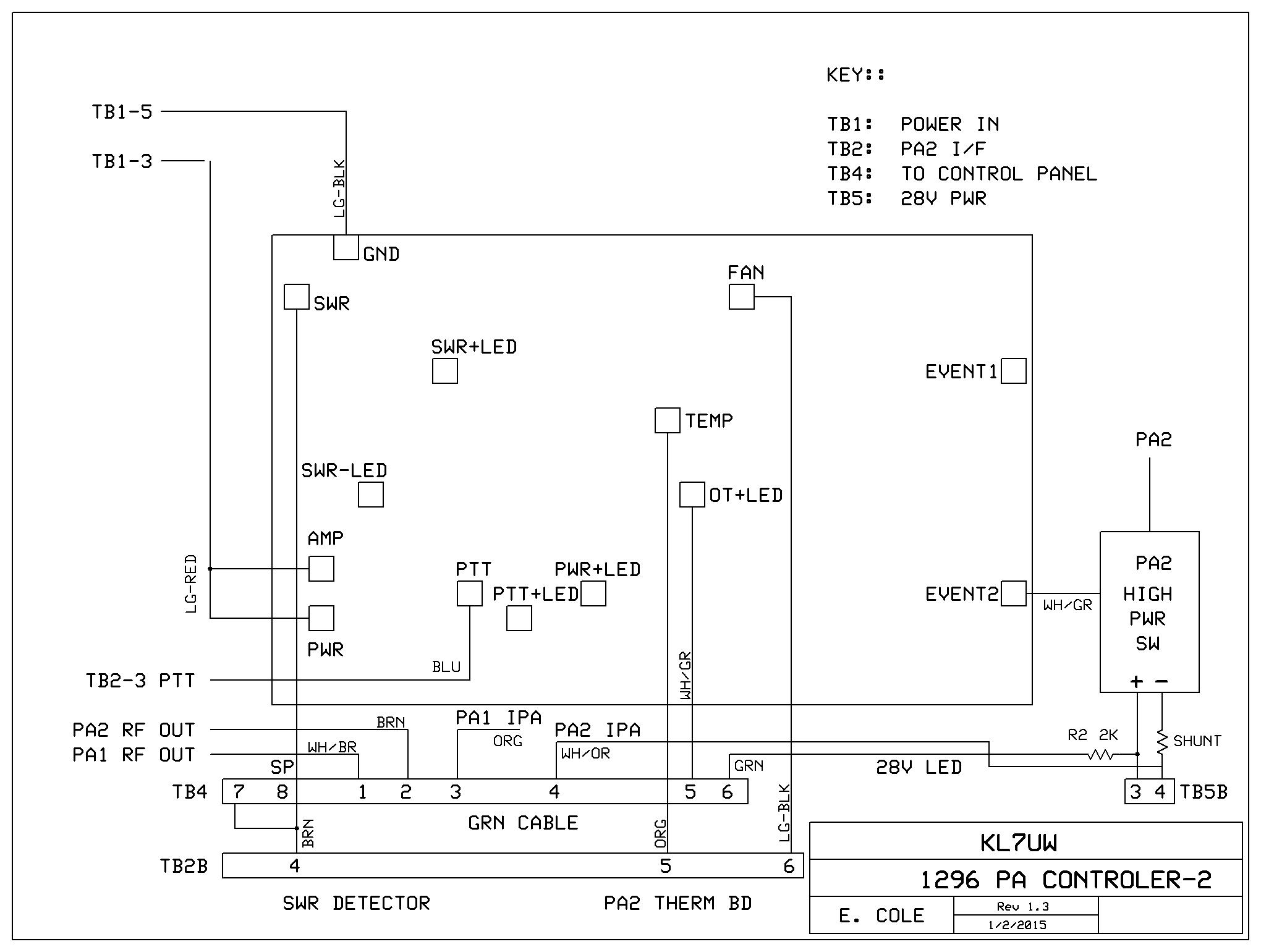
W6PQL Control Board Block Diagrams:

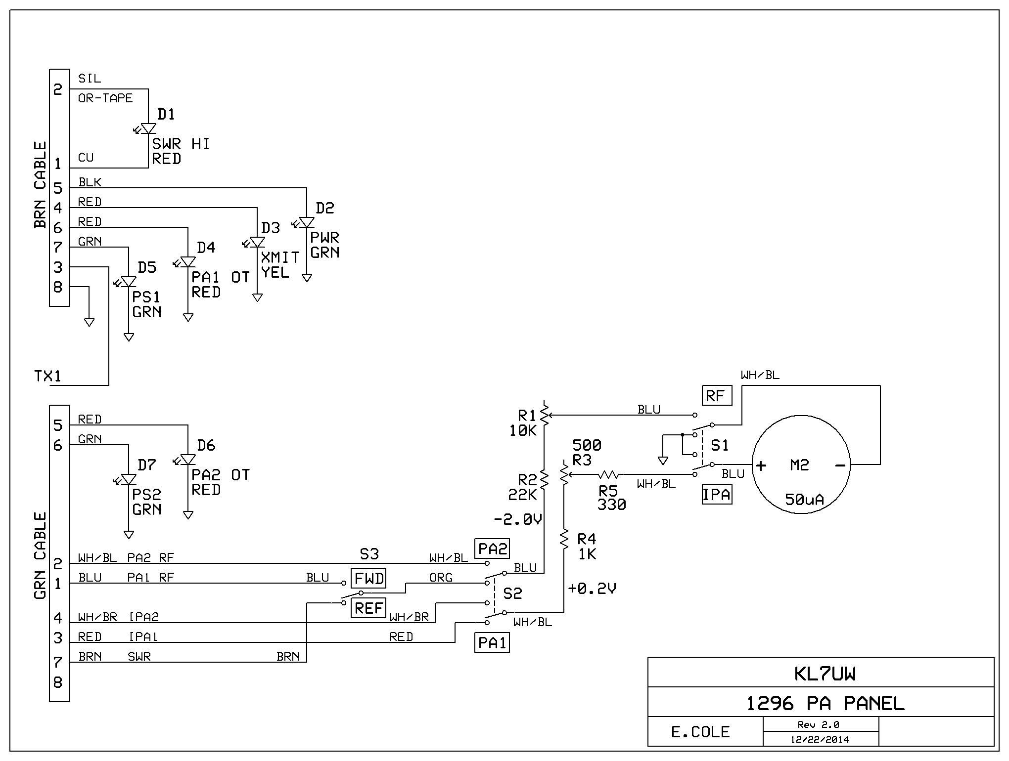
Control Panel Block Diagram:
Return to Home Page:
April 6, 2018 Update
I am selling my 150w W6PQL amps as they will be replaced by a new 600w W6PQL amp. I have built
one 150w amp which was used for several months on 1296 eme. I've removed that amp and bench-tested
it. Max saturated output is 130w with 11w drive. Test Table
Preference will be given to someone wanting to buy the complete 300w amp package, but if
no interest within a week of listing on MoonNet and Microwave reflectors the amps will be
sold separately on first come and best offer basis.
The second amp is a kit which can be purchase as-is or I can assemble it (30-day delivery).
Both amps each include a W6PQL Ultra Control Board and FET dc power switch.
See listing on my For Sale page.
March 11, 2015 Update
With 30w driver amp installed, I have tested up to 130w output. Saturation seems to be appearing so max output
is probably 130-140w. For the meantime I am limiting operation to 120w until I have my Bird 250E element calibrated.
I am QRV for CW and JT65c contacts.
Drive Output Ipa Vc RF Det
10w 120w --- 27.65v 1.6v
Nov. 3, 2014 Update
The first 150w amplifier is completed and tested. Prewiring of control board and amplifier
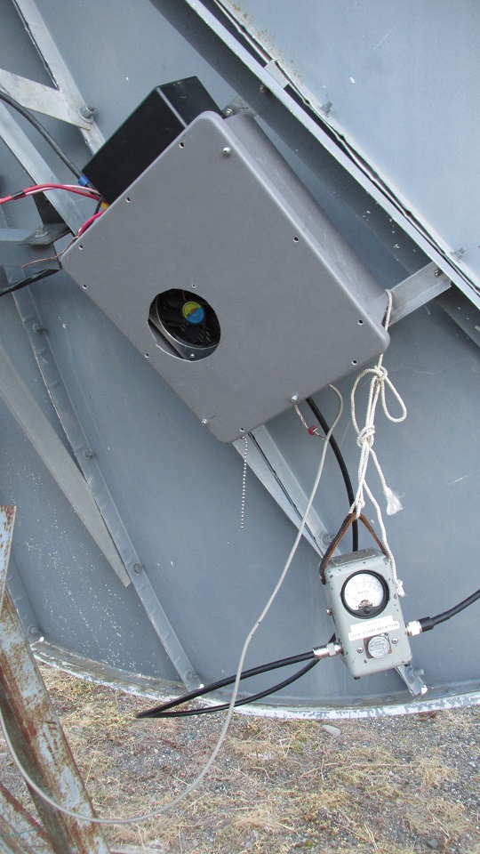
Is being done on the pallet that will be installed in an all-weather enclosure to be attached
to the rear side of the dish in the next two days. (photos soon)
Tests:
Drive Output Ipa Vc RF Det
2w 35w 4.6a 27.7v 1.18v
5w* 80w 9.0a 27.28v 1.67v
5.4w 90w
8.6w 120w 10.3a 27.17 1.96v
Tests with Bird43 power meter and 100E element into 50w coax load.
*Note: 5.2 w is current drive level available at the dish.
Test at the dish: 90w RF output with 27.5v at the PA with the 16-foot No. 8awg dc cable from the 28v PS.
10 amp current shunts were installed but not wired or tested. No reflected RF detected when terminated into the feed horn.
Description of 300W Amplifier Kit from W6PQL that uses four XRF-286 LDMOS transistors.
Schematic Diagram of 150w board:
Photos:


 "
"


W6PQL Control Board Block Diagrams:


Control Panel Block Diagram:

Return to Home Page: