This page describes the construction of a 1500-watt 2m amplifier using an 8877. The design follows
the classic W6PO design which is described in the Eimac Notes. I am using the Triode Board
built by G3SEK (2023 appears no longer avaialble). I purchased the Plate lines and output tuning capacitors as a kit from Harry, WA4OFS(sk).
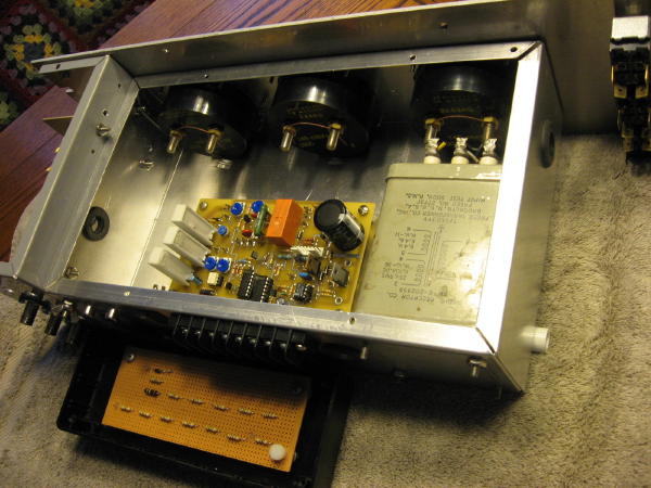
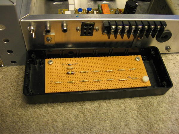
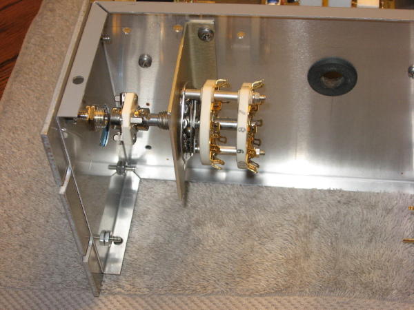
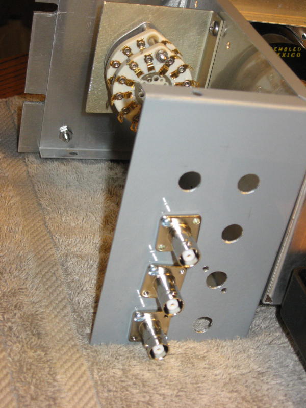
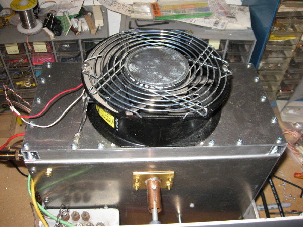
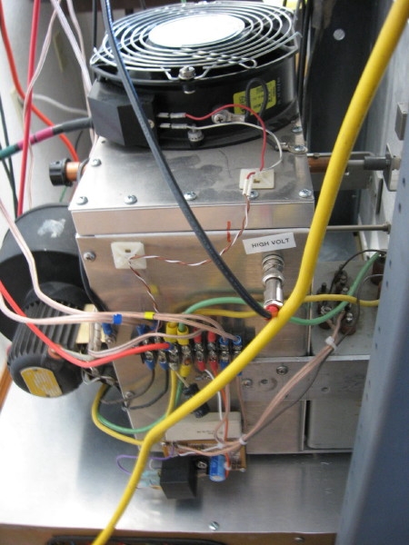
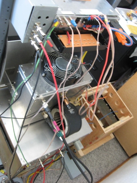
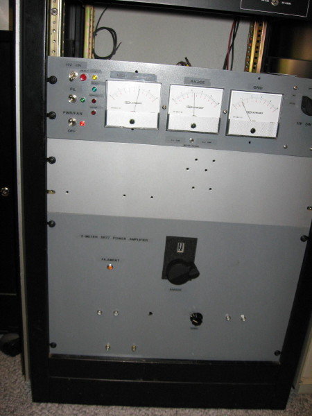
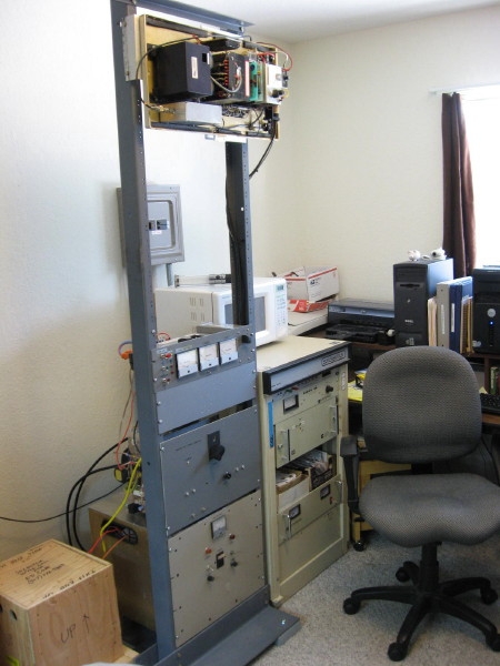
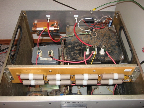
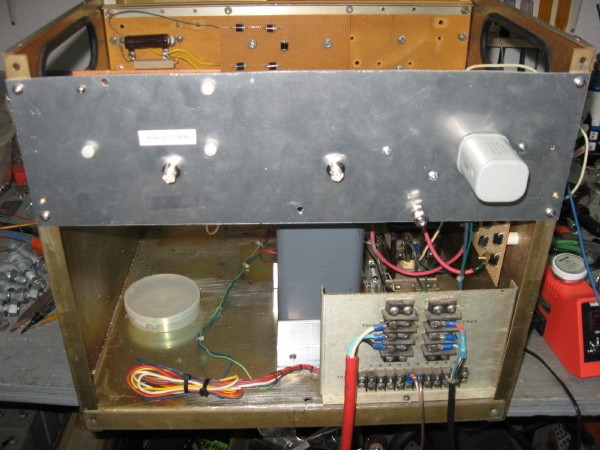
Here are some photos of the amplifier under construction: (click to see larger image)


 Block diagrams of the amplifier showing control, bias, and power wiring: (click to see larger image)

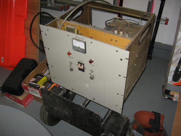
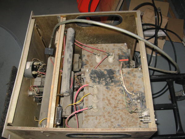
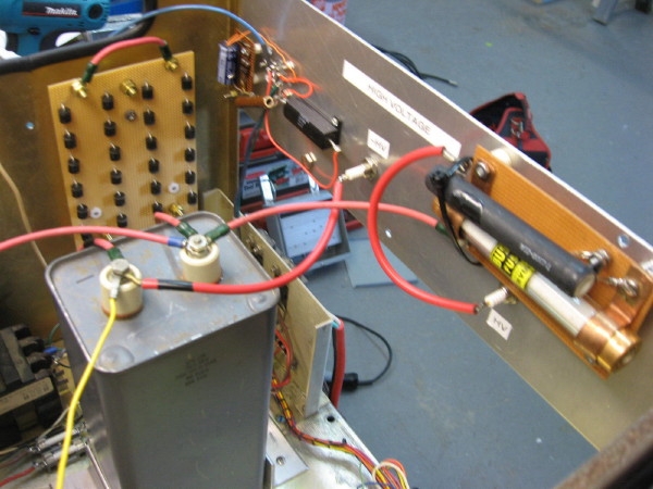
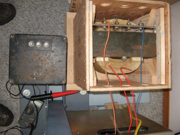
 QRO HV power supply acquired:
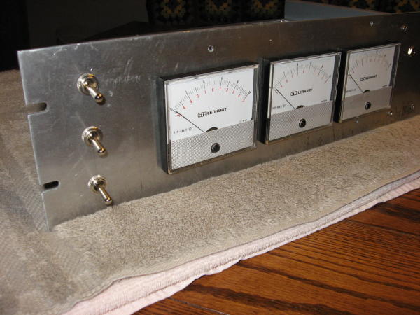
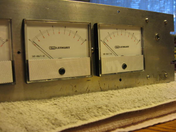
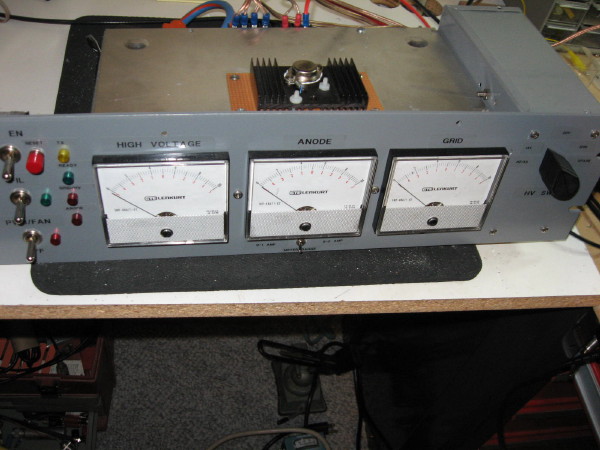
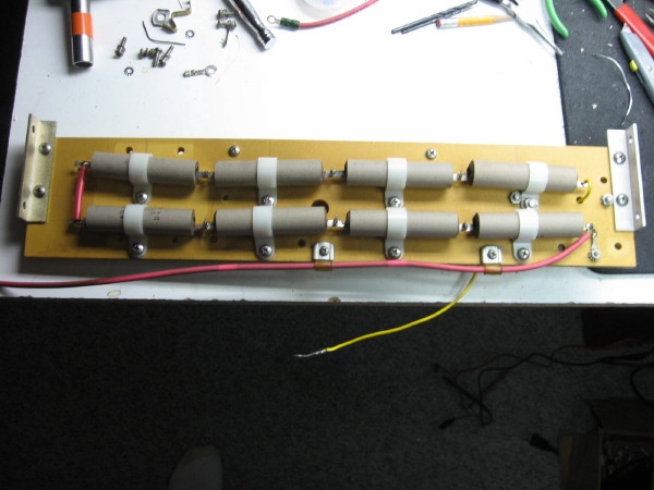
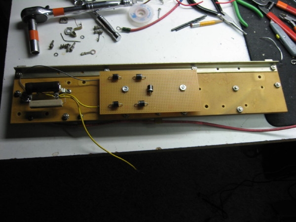
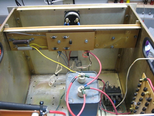
 Here are photos of the assembled PA Control Panel (before wiring):


Testing of 2m-8877:
I discovered that using a galvanized steel screen for the cover of the amplifier enclosure
was not the best choice. Apparently, a magnetic metal is subject to higher circulating RF
currents. First, I mounted the 1/4 wavelength copper lines too high such there was indadequate
clearance between the anode straps and the top cover (3/16-inch). This resulted in a HV flashover
(arc) to occur resulting in a very small spot to appear on the screen directly above the anode
straps (carrying high RF currents).
I deformed the straps to increase the air gap between the anode straps and the enclosure cover.
My solution resulted in RF heating in the area directly above the straps (see photo). Two large
dark circles appeared in the mesh directly above the anode straps.
My solution was to use the original sheet aluminum cover and make a large vent by drilling a pattern
of 3/8-inch holes too form a vent. To this I add a six-inch radial fan above the vent to aid air flow
out of the anode cavity. The cover was raised by using 3/4 square channel as a spacer around
the upper lip of the enclosure. This resulted in roughly 1-inch separation of the anode straps to the
cover. This worked out well, with no HV arcing or heating evident.
I have now run about ten hours time on the amplifier (March 3, 2009), with it preforming very reliably.
Oct. 18, 2010 - Testing the CAI HVPS:
I will try adjusting the ouput load capacitor and more drive to get more RF output. Atempting to drive
the 8877 with 50w using a solid-state amplifier resulted in a flashover on the -HV line.
Dec. 7, 2010 - Testing the CAI HVPS:
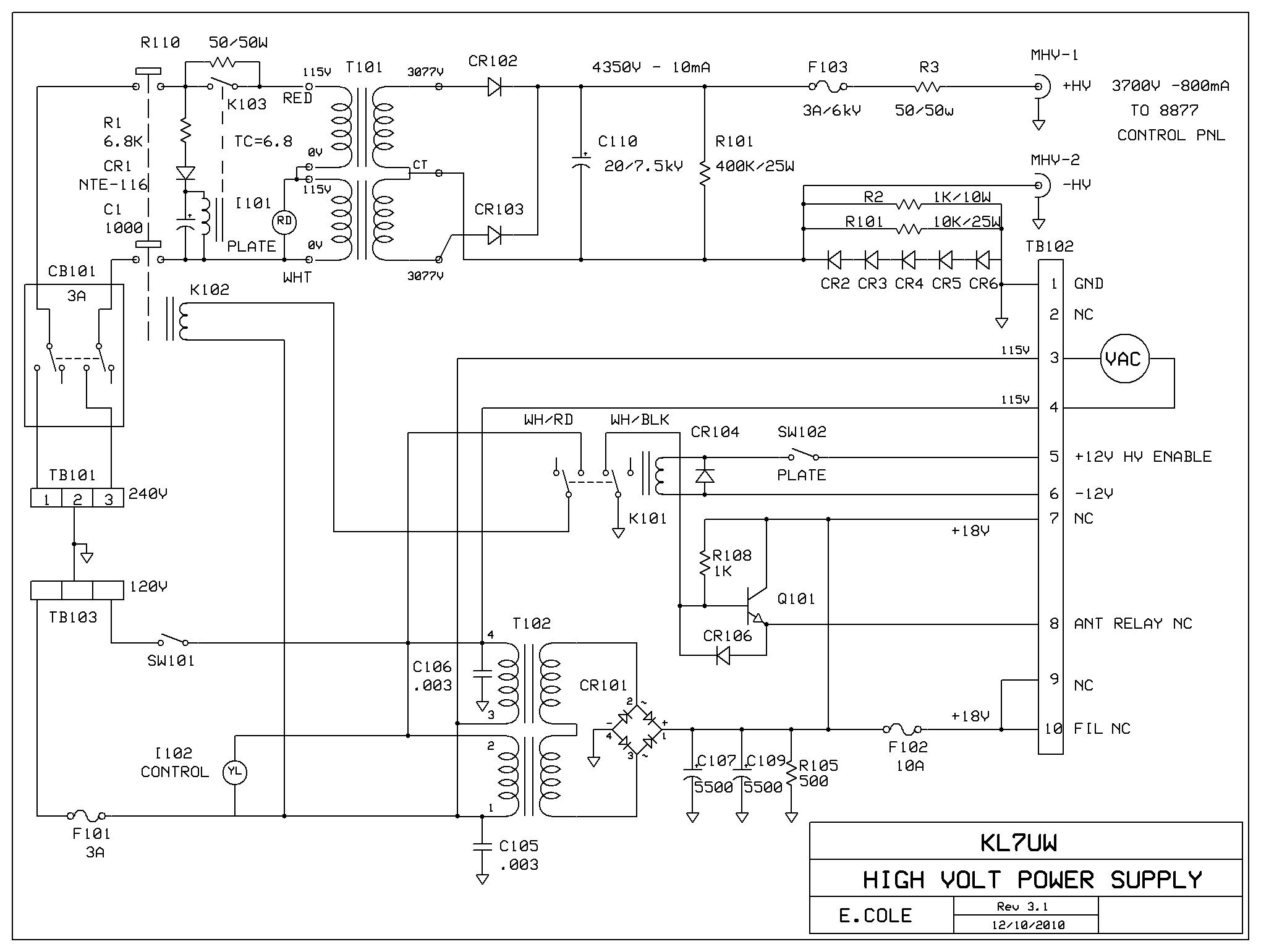
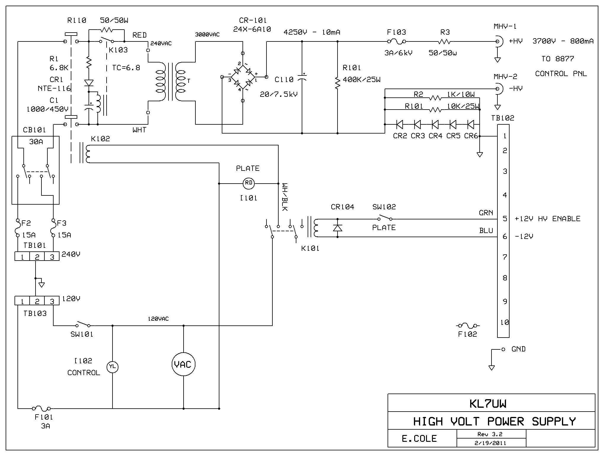
The HV power supply has been modified to capacitive input by removal of the filter choke an redesign of
the bleeder; slow-start circuit on the primary of the HV transformer and relocation of HV surge and fuse
to the HVPS. The Bias control transistor and a mosfet switch were found to be shorted and replaced in
the Control panel. Schematic
 Dec. 8, 2010 - Testing the CAI HVPS:
Dec. 9-12, 2010 - Testing the 2m-8877 Amplifier:
Several days trying to optimize tuning of the 2m-8877 amplifier ended up with a failure
of the coax jumper from the amplifier to the main Bird power meter. A bad connector shorted
out. Subsequent inspection of the jumper showed extensive corrosion in the cable from water
intrusion (this must have occured prior to being installed in the radio shack). The cable has
been replaced with a new run of LMR-400 with new N-connectors (loss=0.27 dB which will result
in 86w being dissipated in the coax when the amp runs at 1400w).
Final measurements that will be used as the published parameters for the 2m-8877:
Dec. 14, 2010 - HV Power Supply Fails:
The power supply ran for two hours in the morning doing meteor scatter at 1300w. At 1810 utc
the mains breaker tripped shutting down the HVPS. Attempts to power up the HVPS continued
tripping the 20 amp breaker. Investigation revealed that the transformer was arcing either from the
case or across the 240vac line. The tranformer input shows a short. Half of the secondary is open.
the other side of the secondary shows leakage to ground (800K indicated with ohm meter).
A replacement HV transformer has been being shipped from Oregon and in process of installation.
Here is the revised HVPS Schematic. QRT on 2m EME, temporarily.
Rebuilt HVPS, Feb. 22, 2011:


 Testing, Feb. 25, 2011:
Testing, July, 2 2011:
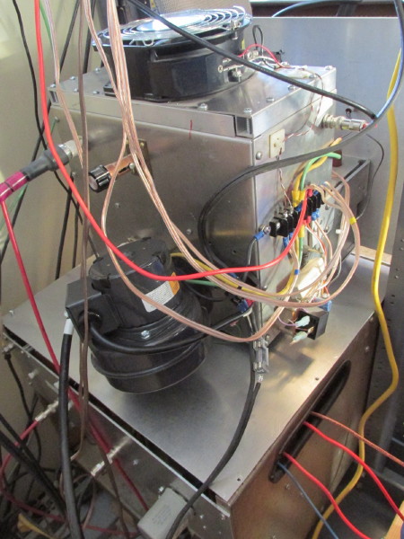
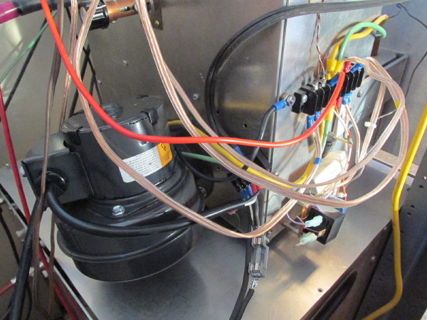
New Blower, November, 2013:
 Amplifier and HVPS Sold in 2018.
Return to 2-meter EME page.