 INSTALLING LINRAD:
The following is for installing Linrad under Windows XP, Vista, or Seven (only).
If you wish to download for other OS like win95, win98, win2000, or Linux go the the Linrad
Homepage for instructions. They will not be covered below:
INSTALLING LINRAD:
The following is for installing Linrad under Windows XP, Vista, or Seven (only).
If you wish to download for other OS like win95, win98, win2000, or Linux go the the Linrad
Homepage for instructions. They will not be covered below:
- Go to the Linrad Homepage link shown at the top of this page and read the procedures for downloading Linrad, then:
- Download the installer: setup-linrad-03.19.exe (681341 bytes)
- Run the installer and use the default folder which is C:\Program Files\Linrad\Linrad-3.19
- Download the Libraries and Binaries: setup-linrad-dll-package-01.exe (614050 bytes)
- Save the setup-linrad-dll-package-01.exe in: C:\Windows\System32
- Find and run the setup-linrad executable file just downloaded
- close all and launch Linrad from the shortcut on the desktop
- Connect the emu-0202 to the computer with a USB2.0 cable
- Turn-on power with right-most knob; green power lamp indicates
- Insert Software CD which should auto-start under XP
- Cancel the new hardware detected dialog page if it pops up
- Select the emu-0202 and open the owner's manual
- Follow the installation instructions and restart the computer when finished
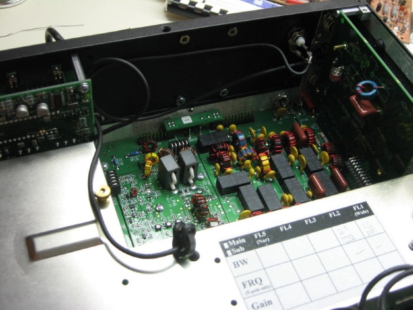
 Front Panel of the emu-0202
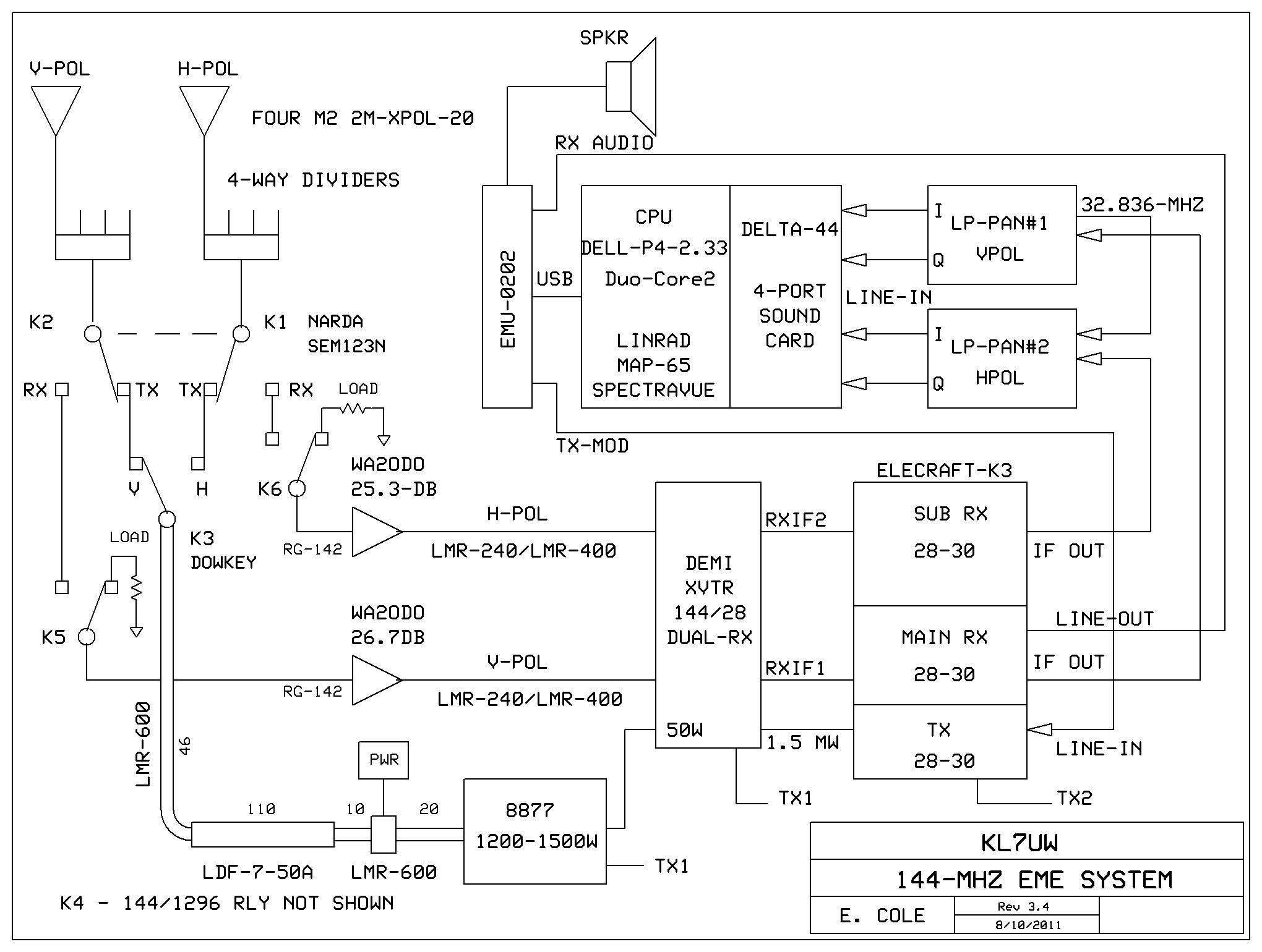
Note: this configuration is for testing the K3 and the LP-Pan with the emu-0202
soundcard and can be used for panadaptor use on HF/6m with the K3. It is not the
configuration planned for use with Linrad.
Front Panel of the emu-0202
Note: this configuration is for testing the K3 and the LP-Pan with the emu-0202
soundcard and can be used for panadaptor use on HF/6m with the K3. It is not the
configuration planned for use with Linrad.
- Connect cables to LP-Pan output from the emu Inputs using two 1/4 to 1/8 inch mono phone connector cables
- Ensure that you connect I and Q cables correctly: I=Left,Q=Right
- Connect computer speakers to the 1/8-inch stereo phone jack (Output)
- Connect LP-Pan to K3 IF output (BNC cable).
- Adjust the Left & Right level adjust controls to "11-o'clock" position
- Press the Direct Monitor Button so the stereo lamp indicates green
- Computer sounds should be heard now
- Turn on the K3 power and tune onto an active band
- Launch emu control panel from the shortcut icon on the computer screen
- Chose a sample rate = 96 KHz
- You can hear radio audio in the speakers by increasing the Direct Monitor Level higher
- The emu manual instructs to adjust Line Levels so "-12" green lamps just flicker but this raises the noise floor too high
- Radio audio is also available for head phones plugged into the emu
- Reset Line Levels to "11-o'clock" for spectrum display
- Panadaptor software will need to be installed for display of spectrum
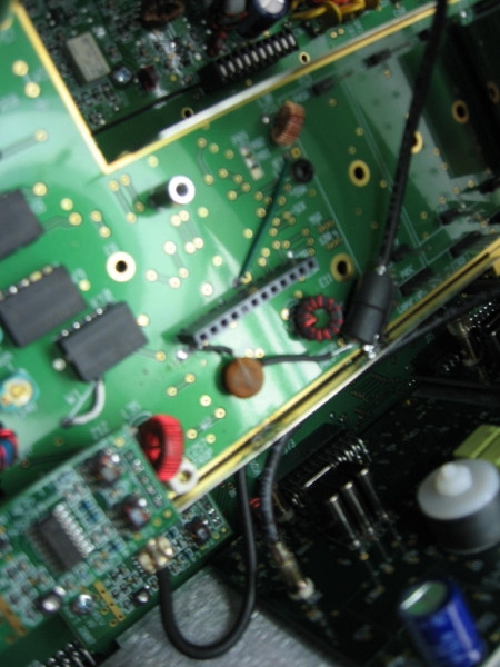
- Strip an eight inch piece of Belden 7805 RF100 RG-174 coax cable and remove about 3/4-inch of the jacket.
- Comb out the braided shield and twist to make a tight ground conductor.
- Slip some heat-shrink tubing over the twisted shield so 1/4 inch is exposed.
- trim one lead of a small .001 uF disc. cer. capacitor to 1/4 inch, bend one lead and insert 1/8-inch in the hole adjacent to "w-3"
- connect the other lead of the capacitor to the center conductor of the coax, after two ferrite beads are slid onto the foil shield of the center conductor; 3/8 inch of the coax should extend beyond the beads.
- strip 3/16 inch of the coax and solder to the unconnected capacitor lead.
- Solder the coax shield "wire" to the tinned metal shield of the KRX3.
- Solder it down at the junction of the KRX-3 pc board so the KRX-3 cover can still seat without interference.
- reinstall the noise blanker pc board.
- Route the coax cable up thru the largest hole in the metal KRX-3 cover, install the sub-receiver cover.
- Once the KRX3 cover is secured, run the coas thru a small toroid winding the coax thru twice.
- The other end of the coax will be connected to a BNC female connector inserted into the hole reserved for the XV144 antenna.
- Connect one of the LP-Pan to the sub-receiver IF BNC connector.
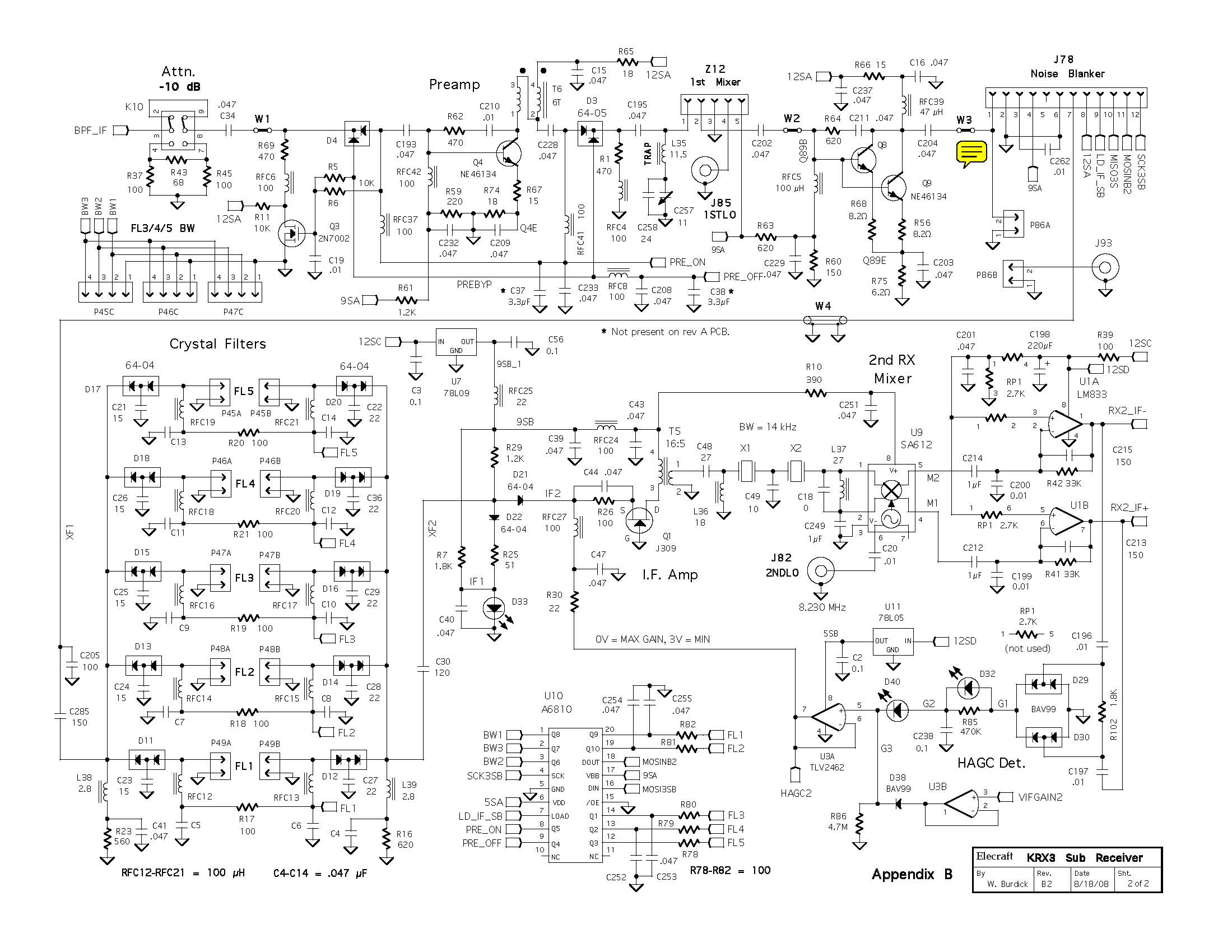
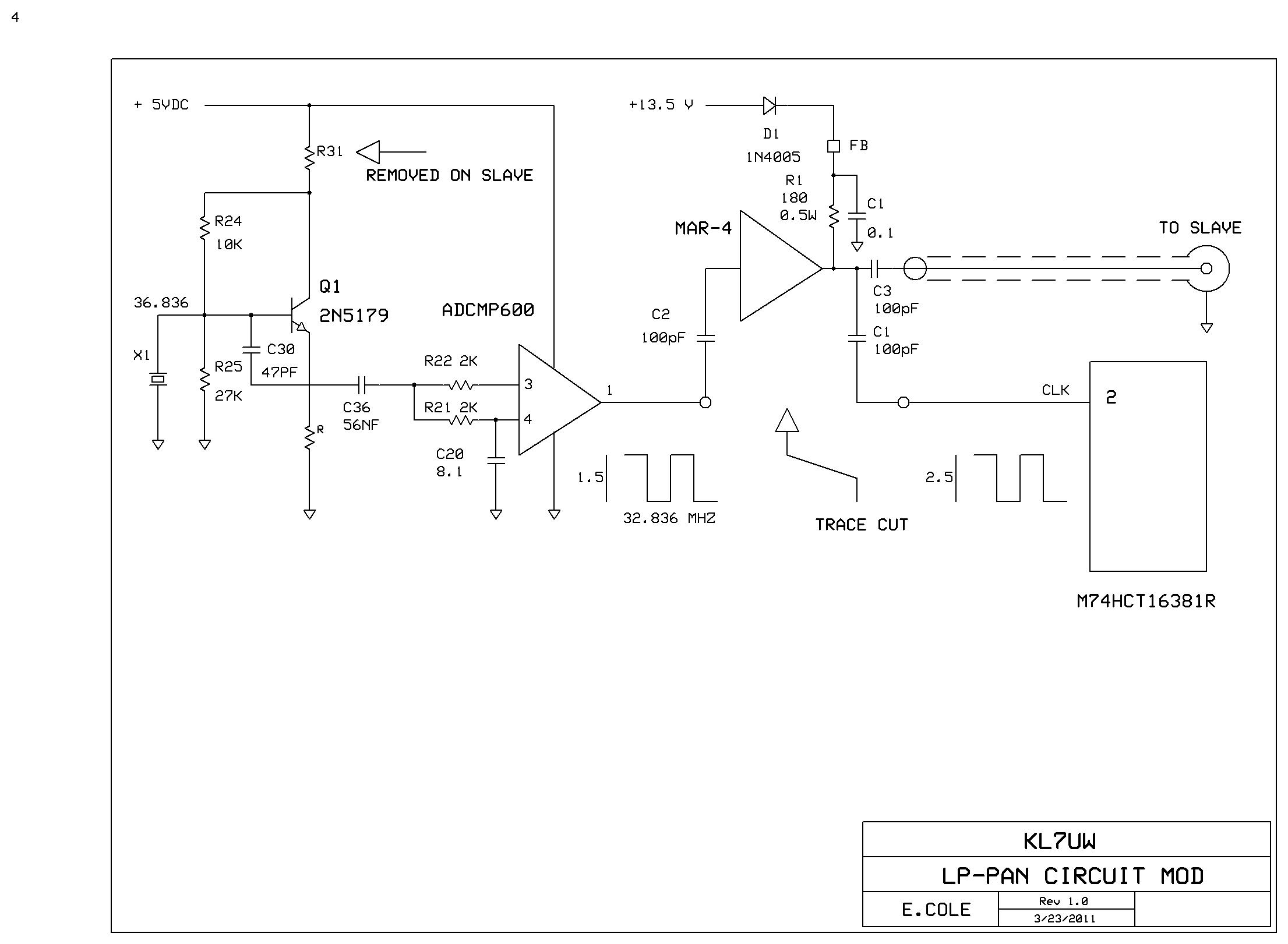
 Modifying LP-Pan to run on a Master Oscillator:
For the LP-Pan to be in phase, the units are run from one master clock. The 32.836 MHz xtal oscillator
in one of the units was chosen as the master, and the ocillator in the other unit disabled. Clock lines
from U11 (ADCMP600) were cut in both LP-Pan. A capacitive divider was installed on the master unit and fed
to the slave unit via coax jumper. I had to add a mmic amplifier (MAR-4 to compensate for loading). The
clock signal needs to be >2.2 Vpk-pk for the IQ-switch to work correctly. The MAR-4 loads down the output
of U11 to 1.5 Vpk-pk but its gain boosts it to over 2.5 Vpk-pk which is enough to drive both LP-Pan.
LP-Pan Schematic from their website.
Modifying LP-Pan to run on a Master Oscillator:
For the LP-Pan to be in phase, the units are run from one master clock. The 32.836 MHz xtal oscillator
in one of the units was chosen as the master, and the ocillator in the other unit disabled. Clock lines
from U11 (ADCMP600) were cut in both LP-Pan. A capacitive divider was installed on the master unit and fed
to the slave unit via coax jumper. I had to add a mmic amplifier (MAR-4 to compensate for loading). The
clock signal needs to be >2.2 Vpk-pk for the IQ-switch to work correctly. The MAR-4 loads down the output
of U11 to 1.5 Vpk-pk but its gain boosts it to over 2.5 Vpk-pk which is enough to drive both LP-Pan.
LP-Pan Schematic from their website.
 INSTALLING the DELTA-44 Soundcard:
- Insert Driver CD which should auto-start under XP
- Follow directions from the CD
- Ignore "Windows Logo Testing" warning - Press continue
- Select "Yes, I want to shut down computer" and click "Finish"
- Disconnect power and other cables on the computer
- Open the computer case
- Observe static electricity discharge procedures
- Insert the Delta-44 PCI Card into an unused PCI slot
- Close the computer case
- Connect sub-D15 cable to the newly installed card connector and to the External Breakout Box
- Reconnect other computer cables
- Turn on computer
- XP will display "Found new hardware" Wizard
- If running Vista or Seven the install is done - disregard the following steps
- Chose "Install software automatically" and click "Next"
- When install is done click "Finish"
- You should see "New hardware installed and ready to use"
- There should be a new icon in the Start Menu
Return to Home Page